Ping Pong LED Clock
How I built and programmed my own Ping Pong LED clock with firework animations.
- Introduction
- Materials
- The Build
- LED Index Look Up Table
- Foreground Modes
- Background Animations
- Potential Improvements
- Conclusion
Introduction
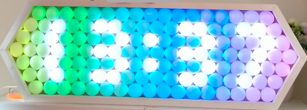
Ping pong balls are great light diffusers and combining them with individually addressable RGB LEDs makes for a pretty display. This ping pong clock can show the time and background animations (more on that later). Since each "pixel" is placed in a hexagonal lattice, the typical digits font for standard 7-segement displays can't be used unless the digits are slanted.
In this blog post, I will describe how I built the thing and my reasoning behind some design choices. Then I will outline how I created my animations so you can fork my repository and create your own animations. At the end, there will be some animations for you to watch!
My code can be found at this repo link.
Materials
I ordered all the materials to build this well before the global pandemic but only got to making it recently. The ping pong balls and LED strip took many weeks to arrive from overseas.
- At least 128 ping pong balls. I used low cost "glossy" plasticky ping pong balls ~$20. Better to use proper ping pong balls that can diffuse the light more efficiently.
- 5 m of WS2128B LED strip at 30 LEDs/m. (This gives you 150 RGB LEDS which is more than the required 128. ~$20)
- 2 m of 3pin wire ~$3. You can use single connection multicore wire as an alternative.
- Some lead-free solder ~$2. Any solder will do really.
- Microcontroller (I used an Arduino Nano Clone ~$3. Not enough RAM for scrolling text animations so consider an ESP32 board?)
- A Real Time Clock with coin cell battery. I didn't have one so I used a software implementation instead. That meant I couldn't keep track of the right time after a powerdown. But hey, a broken clock is right twice a day!
- MDF board to attach all the LEDs onto ~$4.
- Wood Frame ~$5. You will need a miter saw to cut the frame at 60 degree angles.
- Some screws/nails/epoxy to fit the frame together ~$1.
- Lots of hot glue. I used a 30 cm stick ~$1.
- A 5 V power supply. I'm using a phone charger which can provide up to 2 A of current. If you plan to turn all the LEDs to max brightness, you'll need like 8 A but for all intents and purposes, I think 2 A is enough. You can use a
FastLEDsetting to set a limit to the power draw and the brightness will automatically adjust for you.
The original instructable which describes how to build and program the LED clock is a great resource so definitely take a look! In it, he/she uses competition quality ping pong balls rather than the cheap ones I used which tended to be glossy and inconsistent in the amount of plastic for each ball. I'm inclined to agree that the higher quality ping pong balls are way better despite being more costly. The cheap plasticky ping pong balls don't diffuse the light enough and the LED position can seen from behind. If you do choose to use the cheap ping pong balls however, I found that you can recreate the really great light diffusion by stacking two cut halves together. Looking from afar, I can't notice any blemishes (or at least, my mind won't let me).
The Build
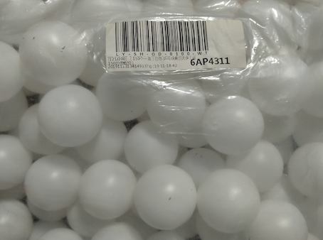
From a bag of 150 ping pong balls,
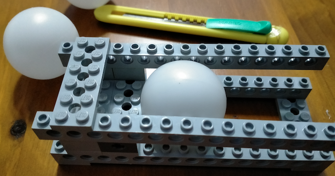
each ball goes into a jig I made using LEGO to hold the ball in place while I used an X-acto knife to slice along the seam. If you don't slice along the seam, you can see the seam when you shine the LED behind it! This is the most tedious part and took me a whole day.
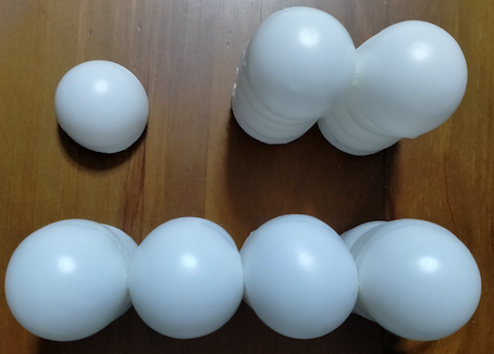
I then used hot glue to double stack each half to improve the diffusion. Once the improved halves are done, I glued two together while aligning it to a flat surface (edge of a tissue box in my case). The instructable used two long lengths of wood to ensure each row is straight - it's impossible to mess up the straight line gluing two pieces together. Then extend to the final shape shown in Figure 6 (2 rows of 17, 2 rows of 18, 2 rows of 19 and 1 row of 20). I used hot glue quite liberally to make the structure rigid but it still ended up rather fragile - not a problem once it's in the frame and glued down.
I cut the LED strips such that the included JST connector both starts and ends the whole thing and these connectors are pulled through a 12 mm diameter hole. This means you can provide 5 V power from both ends. I follwed the wiring shown in Figure 8. Keep in mind the direction shown on the strip! I found that the wiring wasn't noticible after the ping pong balls were placed so didn't bother putting them behind the MDF board like the instructable. Sticky tape was used to temporarilly fix the strip positions while I test for light leakage after placing the ping pong balls on top.
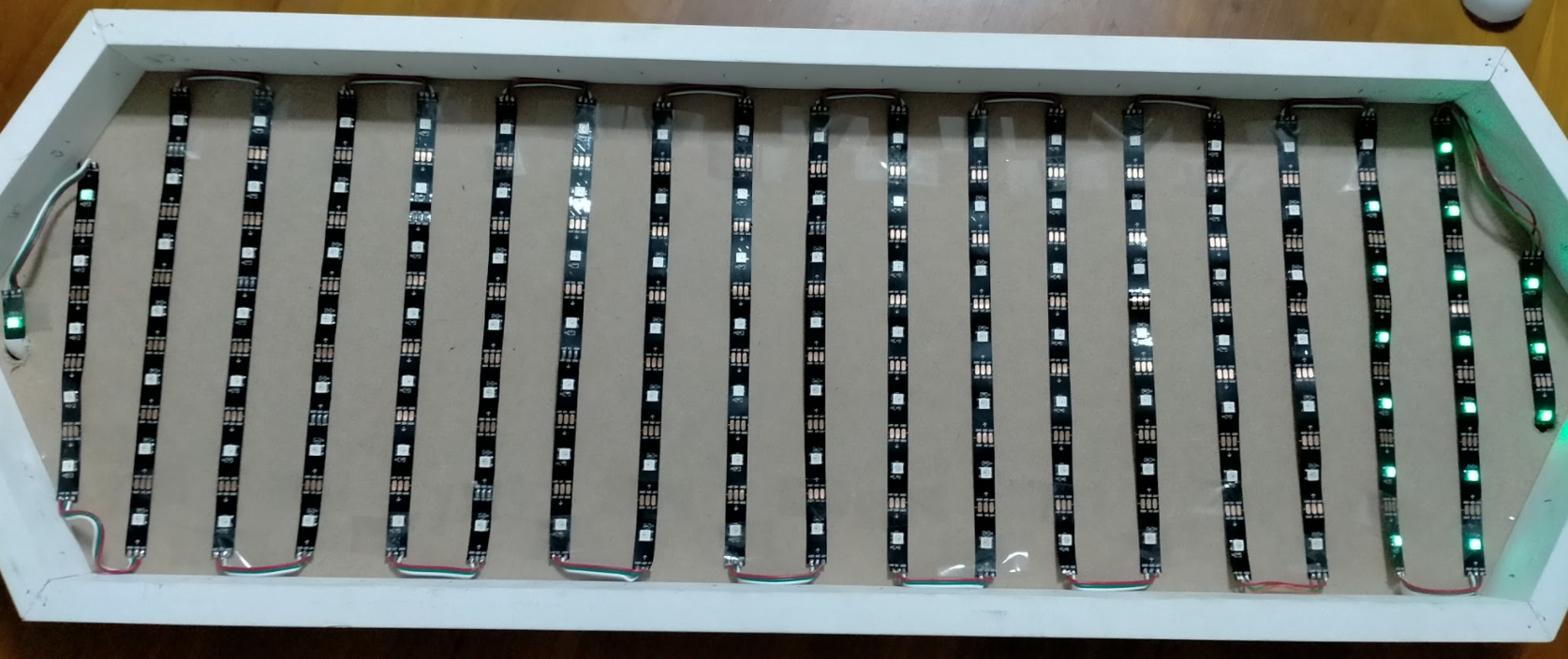
The reason why I'm not providing exact dimensions for the frame is that the dimensions will depend on how well you glue all the ping pong ball pieces together. Since each ping pong ball was 40 mm diameter, the row of 20 should be 800 mm long but mine ended up being 810 mm. With the frame, the overall dimensions was roughly 850 mm long and 290 mm tall.

Before you fix the LED strips in place with more hot glue, turn on all the LEDs and make sure each LED is underneath a ping pong ball. Look up the FastLED library to see how to do this - it's very simple and there are great example codes to run!

LED Index Look Up Table
The crux of my animations rely on knowing which LED number along the connected strip of 128 corresponds to a two dimensional position. From Figure 8, I label each LED by it's strip index which you can see in Figure 9.
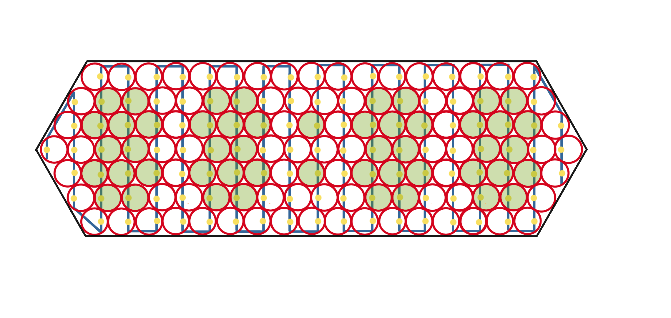

Imagining the display as a parallelogram slanted to the left, I turned Figure 9 into a two dimensional array (look up table) with values corresponding to the strip index. For the positions that don't exist, I put values of 999.
const int led_address[7][20] = {
  {999,999,999,12,13,26,27,40,41,54,55,68,69,82,83,96,97,110,111,124},  // 0th row
  {999,999,1,11,14,25,28,39,42,53,56,67,70,81,84,95,98,109,112,123},    // 1st row
  {999,2,10,15,24,29,38,43,52,57,66,71,80,85,94,99,108,113,122,125},    // 2nd row
  {0,3,9,16,23,30,37,44,51,58,65,72,79,86,93,100,107,114,121,126},      // 3rd row
  {4,8,17,22,31,36,45,50,59,64,73,78,87,92,101,106,115,120,127,999},    // 4th row
  {5,7,18,21,32,35,46,49,60,63,74,77,88,91,102,105,116,119,999,999},    // 5th row
  {6,19,20,33,34,47,48,61,62,75,76,89,90,103,104,117,118,999,999,999},  // 6th row
};
Now that I have access to the row and coloumn in the ping pong display, I went ahead and added custom animations.
FastLED Frame Buffer
I used the FastLED library for controlling all 128 RGB LEDs. After connecting 5 V and GND, the remaining data pin can be connected to any digital pin (I used pin 6). This made the hardware really easy to interface and minimsed mistakes with soldering and wiring. (Imagine controlling all the LEDs with its own digital pin!)
The state of all the LEDs are stored in an array that holds the red, green, and blue values for each LED.
CRGB leds[NUM_LEDS];
FastLED.addLeds<WS2812, LED_PIN, GRB>(leds, NUM_LEDS).setCorrection( TypicalLEDStrip );
Setting Colours
Updating this frame buffer does not update the LEDs until you call FastLED.show(). Before writing to the frame buffer, I first use FastLED.clear() to zero all the LEDs to CRGB::Black.
CRGB::colour_name. Some examples are CRGB::White, CRGB::Yellow, CRGB::Teal, and CRGB::Gray.
You can also use the HSV colour space and set the hue, saturation, and value using CHSV(unit8_t hue,unit8_t sat,unit8_t val) which will automatically convert to an RGB value to be stored. FastLED has two rainbow spectrums - I used the default which spaces out the oranges and yellows more and is visually more "rainbow-like".
Power consumption
Each RGB LED can draw 60 mA and since there are 128 of them, that's 7.68 A. In all my applications, I do not need to turn all the LEDs white on max brightness anyway. I found full brightness too bright and that half brightness was good enough. I used a 5 V, 2 A phone charger. FastLED provides as function to limit the power consumption automatically so that LED brightnesses are modified before writing out the frame buffer. This means you can code your animations assuming full power while testing on a smaller power supply, then change a setting for deployment.
FastLED.setMaxPowerInVoltsAndMilliamps(5,500);
// Also, see this function
// FastLED.setBrightness(  BRIGHTNESS );
For example, if the value is 11.5 after FastLED adjusts the value, FastLED will use temporal dithering to make it appear as 11.5 by quickly switching between 11 and 12. Neat!
Timing
Each RGB LED takes around 30 us to be written. To update the whole clock display, the whole process takes 3.84 ms. Theoretically, that means the max refresh rate is 260 Hz but it takes time to clear the frame buffer, cycle through the look up table, compute colour values and write the new animations. In practice, I found a 20 Hz refresh rate was plenty for smooth animations.
Instead of using the Arduino delay() function for timing, I used FastLED.delay() instead as it allows for temporal dithering as described above.
FastLED will turn off interrupts temporarily while updating the LED strip due to the tight timing needed to write to the LEDs.
Foreground Modes
When programming the animations, I decided that it would be sensible to segregate the time (and any text?) to the foreground while keeping the rest to the background. The foreground LED colour values will overwrite the background values.
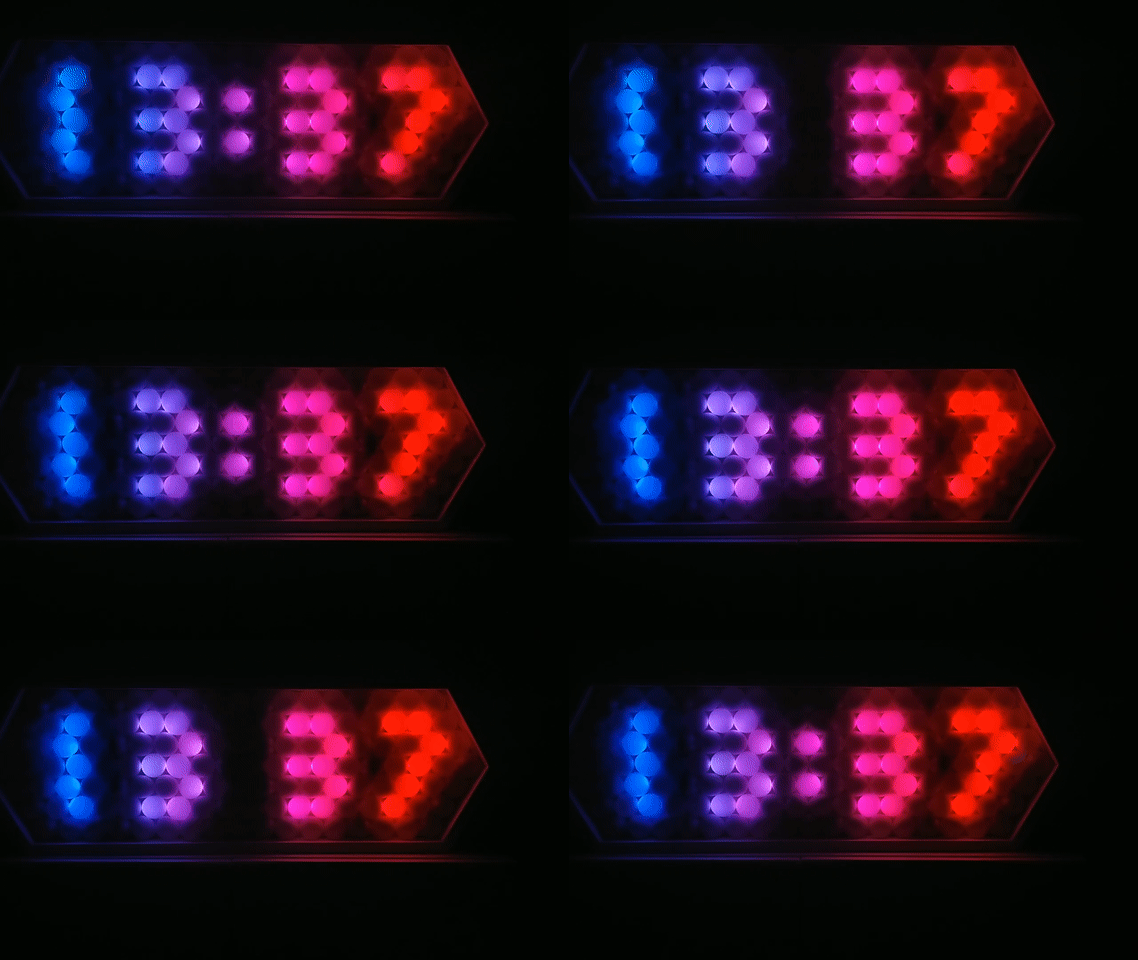
Here's what it looks like displaying the time in rainbow colours with a black background.
Slanted Digits
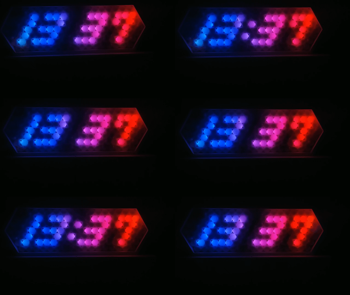
I also have an option to make the time appear in slanted mode as well as a no time option. The no time option is great for seeing the background animation. In practice, you can mix and match foreground and background modes.
Background Animations
Rolling Rainbow
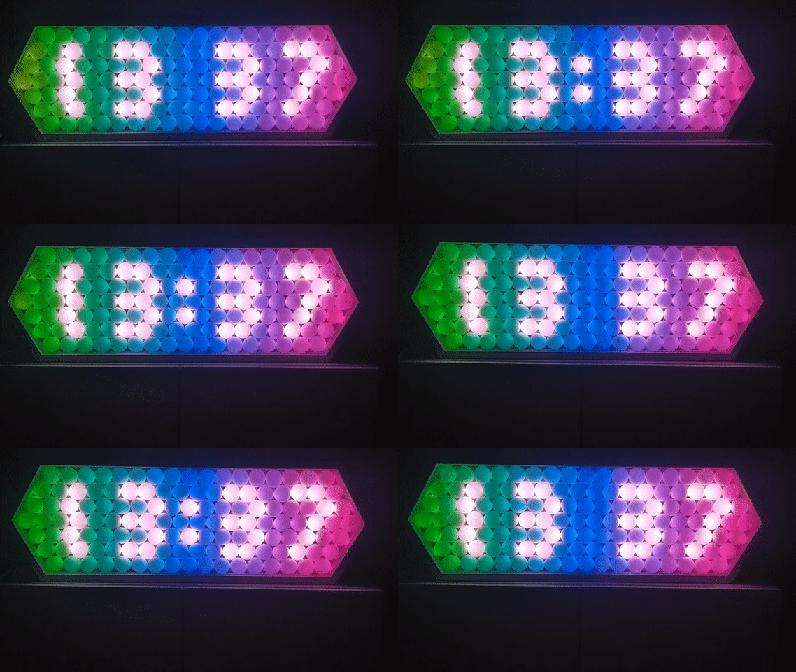
The rainbow background works well with either the foreground set to CRGB::White (as shown in Figure 12) or CRGB::Black.
Twinkle
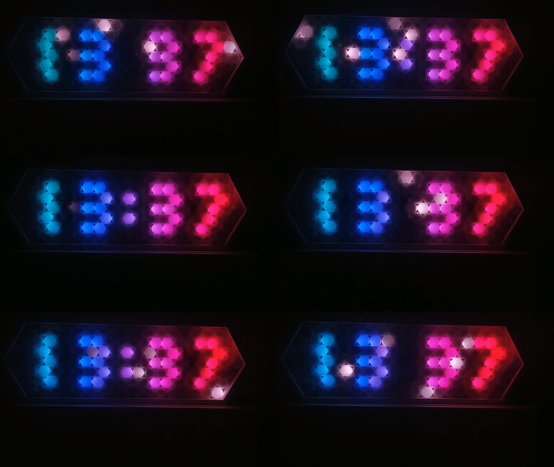
In this one, I randomly chose LEDs to flash white and fade away.
Storm
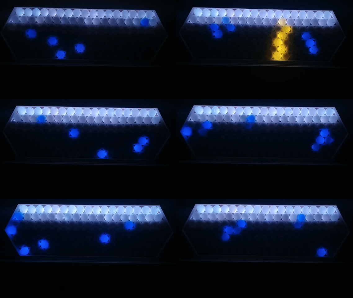
In creating this storm animation, I wanted a fast way to generate random numbers. It just so happens that FastLED provides random8 which I used liberally to generate a raindrop's path downward (and the lightning strikes!).
- Interviewer: Your resume says you are quick at generating random numbers. Give me a sequence of random numbers.
-
random8: Here you go.... - Interviewer: That doesn't seem random to me....
-
random8: But it was quick!
Note:random8is advertised as fast and is not truly random but for me, it is random enough.
Campfire
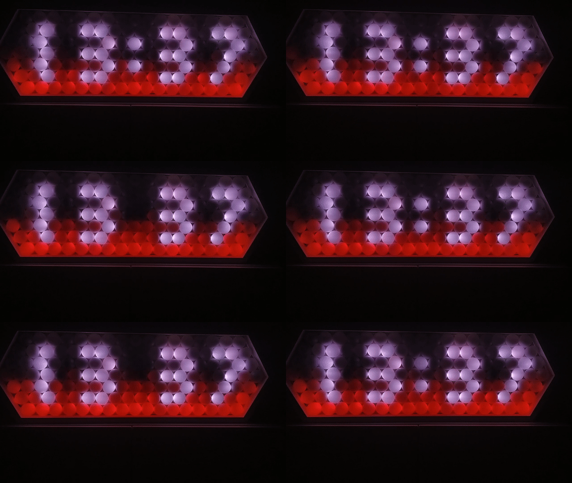
To make this firey animation, I just used random8 to generate brightness values for the bottom four rows. Each row up is slightly less bright. I also randomly shifted the red hue towards orange.
Fireworks
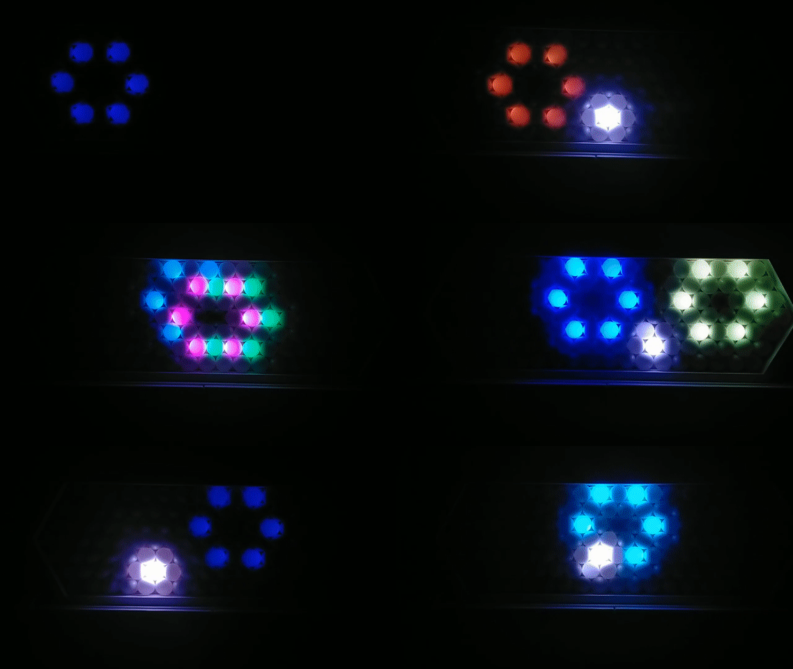
The fireworks animation was by far the most difficult but it looks really impressive (at least to me). The hexagonal pattern to the LEDs naturally lent itself to show an explosion of light in 6 directions. Since each LED has two LEDs directly above, I used random8 to choose Whether the firework rises to the left or the right. More random8 was used to change the explosion height to two different rows and the hue. Finally, I then dim the LEDs to similate the fireworks fading away.
General Animation Method
For each style of animation, I used a struct to define a type that defines the state of the animation. For example, let's look at the fireworks animation. In the code snippet below, the firework type holds the starting $x$ position in the bottom row, the direction going north-west or north-east in the hexagon lattice, the stage or the current step in the animation sequence, the randomly generated hue, and the height offset that determines which row to explode. I then create an array of these struct with size defined by MAX_FIREWORKS.
#define MAX_FIREWORKS     12
struct firework_t {
  int pos       = -1; // LED number in last row
  int direction = 0;  // 0 is left, 1 is right
  int stage     = 0;  // remember where each firework animation is up to
  char hue      = 0;  // colour of each firework
  int height_offset = 0; // sometimes lower by one.
};
The next frame as defined by the user's REFRESH_RATE steps through the animation stages and sometimes randomly starts a new firework should the number of current fireworks be less then MAX_FIREWORKS with some probability. I then loop through all the array and redraw the LED states into the frame buffer according to each fireworks' current animation stage. All that's left is to define what each stage or step looks like and I used if/else if statements to do the job. The same method is applied for the twinkle and storm animation.
Together with the LED index look up table defined by a left-ward sloping parallelogram in Figure 9, and this struct based rasteriser method, it is relatively straightforward to generate your own neat animations!
Low memory available, stability problems may occur and the RAM usage is >90%, be wary that your animations may freeze as it did for me. I made it work by lowering MAX_FIREWORKS and MAX_RAINDROPS until the freezing disappeared but it’ll be better to use a microcontroller with more RAM.
Potential Improvements
Here is a list of improvements I could make to my ping pong LED clock:
- Use a hardware RTC rather than use software
- Implement scolling text
- Use FastLED colour palettes
- Attach light sensor and auto-adjust FastLED brightness
- Attach PIR motion sensor and turn on display when there is someone to look at it
- Attach temperature/humidity/pressure sensor and display stats
- Connect to Wifi (e.g. using an ESP32)
These improvements will require more hardware that I don't have right now... but you can totally put them on your shopping list when you order the materials to make your own ping pong LED clock and show me what you make!
Conclusion
We saw how I put together a ping pong LED clock inspired by an instructable and some animations. Both my hardware and software design choices were explained and my code is freely available at this GitHub repo.
I hope I inspired you to make your own ping pong LED clock with your own cool animations! Let me know how it goes in the comments below!