Understanding GPU Tessellation
An introduction to GPU tessellation. Python code is provided to run the visualisation.
Understanding Tessellation
What is Tessellation
Tessellation is a feature that converts a low-detailed surface patch to a higher detailed surface patch dynamically on the Graphics Processing Unit (GPU). Using a low resolution model with a few polygons, tessellation makes rendering high levels of detail possible by subdividing each patch into smaller primitives.
This blog post will outline how tessellation fits into the graphics pipeline and how to understand the various parameters needed for tessellation including tessellation factors, partition type, and output domain. Finally, I provide code to run a tessellation visualisation including an interactive widget so you can experiment with the various parameters.
Benefits of Tessellation
According to DX11 Tess Docs, the benefits are:
- Lower memory and bandwidth requirements.
- Allows continuous or view dependent details to be calculated on the fly.
- Improves performance by performing expensive computations at lower frequency (doing calculations on a lower-detail model). For instance, calculations for collision detection or soft body dynamics.
A graphics pipeline is a series of functions that transforms inputs (primitive data such as points, lines or triangles) into outputs for rendering. Primitives refer to the atomic or irreducible objects the system can handle. To add tessellation, the graphics pipeline requires three new stages.
Pipeline Stages
The DX11 graphics pipeline consists of a series of stages shown in Figure 1.
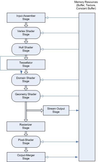
A description of each stage is summarised in this itemised list:
- Input-Assembler Stage
Read primitive data and assemble them into primitives for other stages (e.g. line lists, and triangle strips)
- Vertex Shader Stage
Processes the assembled vertices and applies operations such as transformations, skinning, morphing, and per-vertex lighting. > Single input vertex and single output vertex.
- Tessellation Stages
Breaks up a patch of control points into smaller primitives and thus create higher detailed features.
- Geometry Shader Stage
Operates on vertices and can generate output vertices
- Stream-Output Stage
Continuously output vertex data from geometry shader to buffers
- Rasterizer Stage
Converts primitives into a raster image for displaying.
- Pixel Shader Stage
Operate on a per-pixel level and can change lighting, etc using the available constant variables, texture data, and others.
- Output-Merger Stage
Generates the final rendered pixel colour, determines which pixels are visible and blending pixel colours.
The tessellation stages consistes of three new stages which are:
- Hull-Shader (HS) Stage
Computes patch constants (such as tessellation factors) and other parameters for the tessellation stage. Performs any special transformations on the input patch data.
- Tessellator (Tess) Stage
A fixed function that partitions a geometry into smaller primitives and outputs u,v coordinates of the vertices and assembly order.
- Domain-Shader (DS) Stage
Calculates vertex position that corresponds to the each u,v coordinate.
OpenGL uses the names Tessellation Control Shader, Primitive Generator, and Tessellation Evaulation Shader to refer to the HS, Tess, and DS respectively.
As an aside, the word “shader” refers to an operation that transforms four input numbers into four output numbers. Historically, a shader was used to change the brightness of pixels (RGBA values) but now encompasses more general operations and the name has stuck.
OpenGL and DX using different winding order. The winding order determines the order the vertex stream arrives and this information can be used to check if a patch is facing the screen or away from the screen.
The parameters for the Tessellator stage are: winding order, tessellation factors, partitioning type, and primitive type.
Tessellation Factors
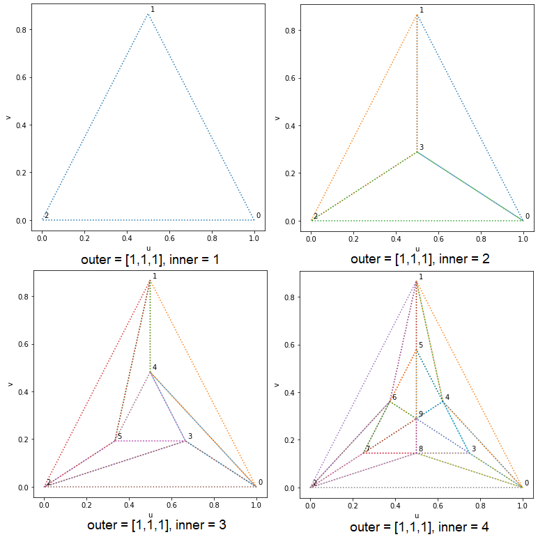
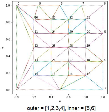
Tessellation factors specify how much each edge needs to be partitioned. For example, a tessellation factor of 1 means no partitioning and a tessellation factor of $n$ means partition that edge into $n$ parts. There are two types, inner and outer factors.
Inner Factors
The inner factor specifies how the interior is partitioned. When this factor is even, the centre of the output domain is a degenerate point. For example, an inner factor of 1 means no inner partitioning and a tessellation factor of $n$ partitions the output domain into $\text{floor}(n/2)$ smaller versions of the output domain shape.
Outer Factors
This specifies how the outer edges of the output domain are partitioned.
Partition Type
Integer
Integer refers to what values the tessellation factors can take. In this case, the valid values are $1,2,…,64$.
Power of 2
Same as integer but the valid tessellation factors are powers of two. That is $2^0,2^1,…,2^5,2^6$ with the maximum tessellation factor of 64.
Fractional
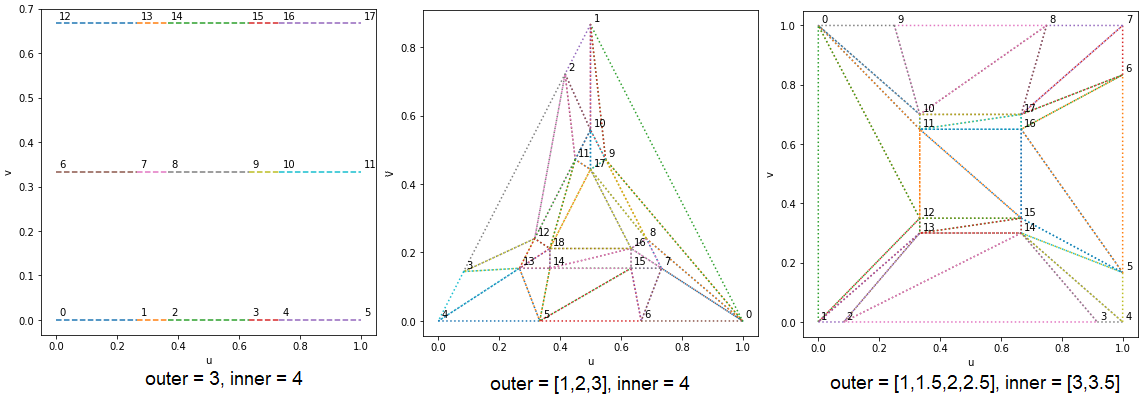
Fractional partitioning allows for a mix of normal and small segments and these correspond to the integer value and fractional value of a tessellation factor. Since each control patch consists of many primitives that can share sides and have a shared tessellation factor, the output primitives need to be symmetric. This symmetry brings about two cases which differ in the location where new verticies are generated: an odd and even parity.
Odd
New vertices are generated from the corners.
The number of segments on an edge is always odd so a tessellation factor of 5 would give five equally spaced segments. If the tessellation factor was 5.1, there would be seven segments, two of which are small and near a corner.
Even
New vertices are generated from the midpoint.
The number of segmenst on an edge is always even so a tessellation factor of 4 would give four equally spaced segments and if the tessellation factor was 4.1, there would be six segments, two of which are small and near the midpoint.
Output Domains
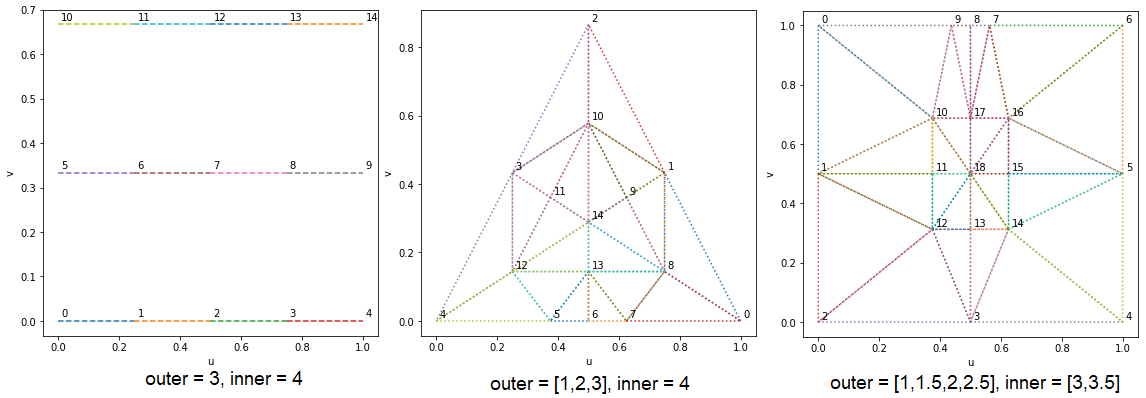
We have already seen what the three types of output domain are: isoline, triangle, and quadrilateral. In the case of a quadrilateral, the output primitives can be triangles or quadrilaterals.
Isoline
For an isoline, the outer tessellation factor is rounded up to the next integer and fractional partitioning only affects the inner tessellation factor. The number of parallel lines is given by the outer tessellation factor while the partitioning of each segment is described by the inner tessellation factor. The outer and inner factor are also known as line density and line detail.
Triangle
For a triangle, barycentric coordinates represent a 2D position using three numbers ($\alpha, \beta, \gamma$) with the condition that $\alpha+\beta+\gamma = 1$. This means there are only two free parameters and is directly related to u, v coordinates using a coordinate transform. Barycentric coordinates allow the same partitioning strategy to be applied regardless of being a Triangle or Quadrilateral.
Barycentric Coordinates
Barycentric coordinates can be understood as a ratio of areas with $A$ representing the total area.
The coordinates ($\alpha, \beta, \gamma$) must sum to unity because the sum of each component subtriangle area must equal the total area of the original triangle. Furthermore, the coordinates are between 0 and 1 because the point $\mathbf{x}$ defines a point within the large triangle. If any of the coordinates are negative or greater than 1, this would corespond to a point outside the allowable triangle.
$\mathbf{b-a}$ and $\mathbf{c-a}$ span an linearly independent vector space and are the basis vectors for a triangle with origin $\mathbf{a}$.
So the “colour” coordinate at point $\mathbf{x}$ is some linear combination of the triangle vertices.
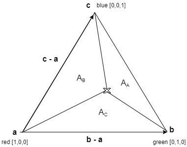
The DX11 Tessellation spec always returns two values: $u$ and $v$, to the third parameter needs to be computed using the unity condition of Barycentric coordinates - that is, $w=1-u-v$.
Quadrilateral
For the quad output domain, the coordinates $u$, and $v$ represent the familar $x$ and $y$ axis of Cartesian space.
Visualisation
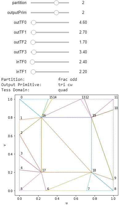
I have taken the DX11 Spec for tessellation1, compiled it and made a python script2 to run the C++ code with customisable parameters. You can play around with the tessellation factors and output domain type and get a feel for how it all works. The steps are:
git clone https://github.com/YiweiMao/tessDX
cd tessDX/
make
Then in a python shell, execute the following:
from pytess import *

# for one instance of tessellation
# if len(tfs)==2, isoline. elif len(tfs)==4, tri. elif len(tfs)==6, quad.
Tessellator(partition=PART_INT,outputPrim=OUTPUT_TRIANGLE_CW,tfs=[1,2,3,4]).doTess()

# for interactivity. Change the sliders to see the updated tessellation
interact(showTess,partition=(0,3,1),outputPrim=(0,3,1),outTF0=(1,64,0.1),outTF1=(-1,64,0.1),
                 outTF2=(-1,64,0.01),outTF3=(-1,64,0.1),inTF0=(1,64,0.1),inTF1=(-1,64,0.1))
Conclusion
Tessellation is a useful GPU feature that can dynamically increase the level of detail on a surface for rendering. We explored how the fixed function tessellator stage fits into the graphics pipeline and what the various parameters mean. We learned how to interpret inner and outer tessellation factors, integer and even/odd fractional partitioning, and isoline/triangle/quadrilateral output domains. Most importantly, I leave you with a tool which you can use to visualise the tessellated output for a given set of parameters.